
A project that had been on my shack’s list of things to do for quite some time was to replace the burned out bulbs in my rotor controllers and apply a couple upgrades while I had them open. Currently the station here has two rotors and controllers. The first is a Yaesu G-1000DXA that I bought used from Jack, W1WEF, and is installed on the tower under the Hexbeam. The other is a G-450A, which was originally purchased for the Hexbeam, but now turns the 40-2CD that goes up on an AB-577 tower during contest season. Both of the boxes needed their hard-wired bulbs replaced (I prefer the soft glow of an incandescent bulb over the available LED mods) and I needed to add the rotor maps that I had purchased from CQMaps.
I had also been on the lookout for a low-cost computer interface that would allow me to adjust the controller’s azimuthal angle directly from the logging software instead of reaching over to push and hold down the switches on the face of the box. I had previously looked into the interface sold by Idiom Press (now Hamsupply.com), but they had received some negative feedback regarding their customer service before they sold their company and they only had an interface for the G-1000DXA. Lucky for me, Scott, W4PA, announced just before Dayton that Vibroplex is now the US distributor for Easy-Rotor-Control (ERC), a German company making a rotor interface that I’d heard good things about. A year or so ago I had looked into ordering one directly from ERC, but didn’t want to deal with international shipping. Now that Vibroplex was carrying them, ordering would be simple and when I went to Dayton last May, I picked up an interface for each of the controllers.
If you’ve never opened up a Yaesu controller to replace a bulb, the process can be somewhat of a pain, but I’ve opened up both of these boxes to do repairs in the past, and after the first time, it becomes much easier. I had also previously purchased the rotor map insert for the G1000DXA, but had installed it in the G-450A as a test for James, N4EGA @ CQMaps to help him determine if he needed to create a different version for each controller model. It did fit, but needed some adjustments, so I left it in until James had finished coming up with the new version for the G-450A.
Scope of Work
- Replace bulbs in both controllers
- Move map insert from G-450A to G-1000DXA and add new insert into G-450A
- Build and install computer interface in the G-450A and plug in interface for G-1000DXA
- Configure interfaces for both N1MM and DXLabs logging software
Getting the parts
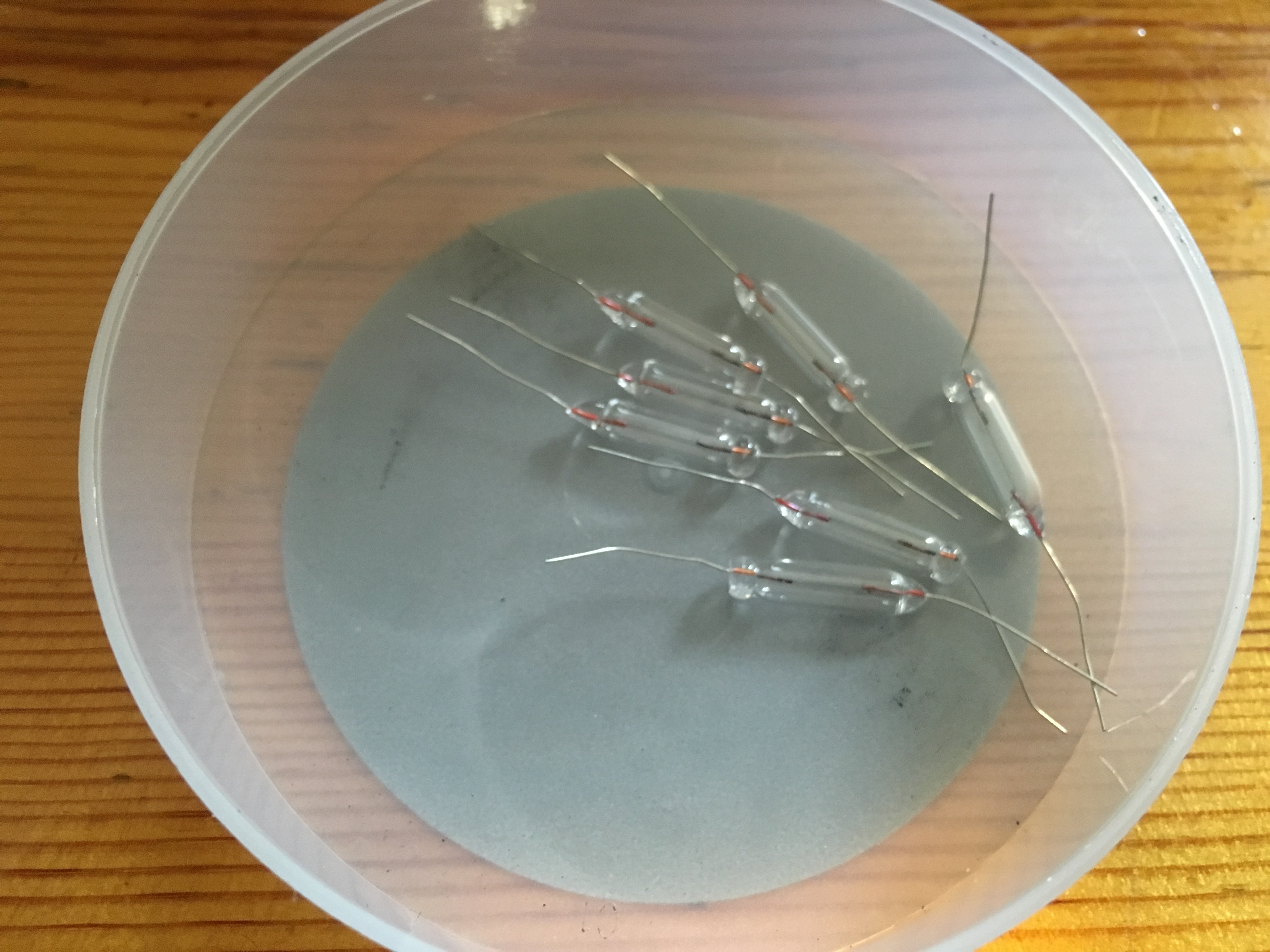
I already had bulbs that I had purchased in the past. They cost nearly nothing, so it makes sense to order a dozen even if you only need one. This will give you plenty of replacements and a couple extra so you can be the club hero when a friend needs a replacement.
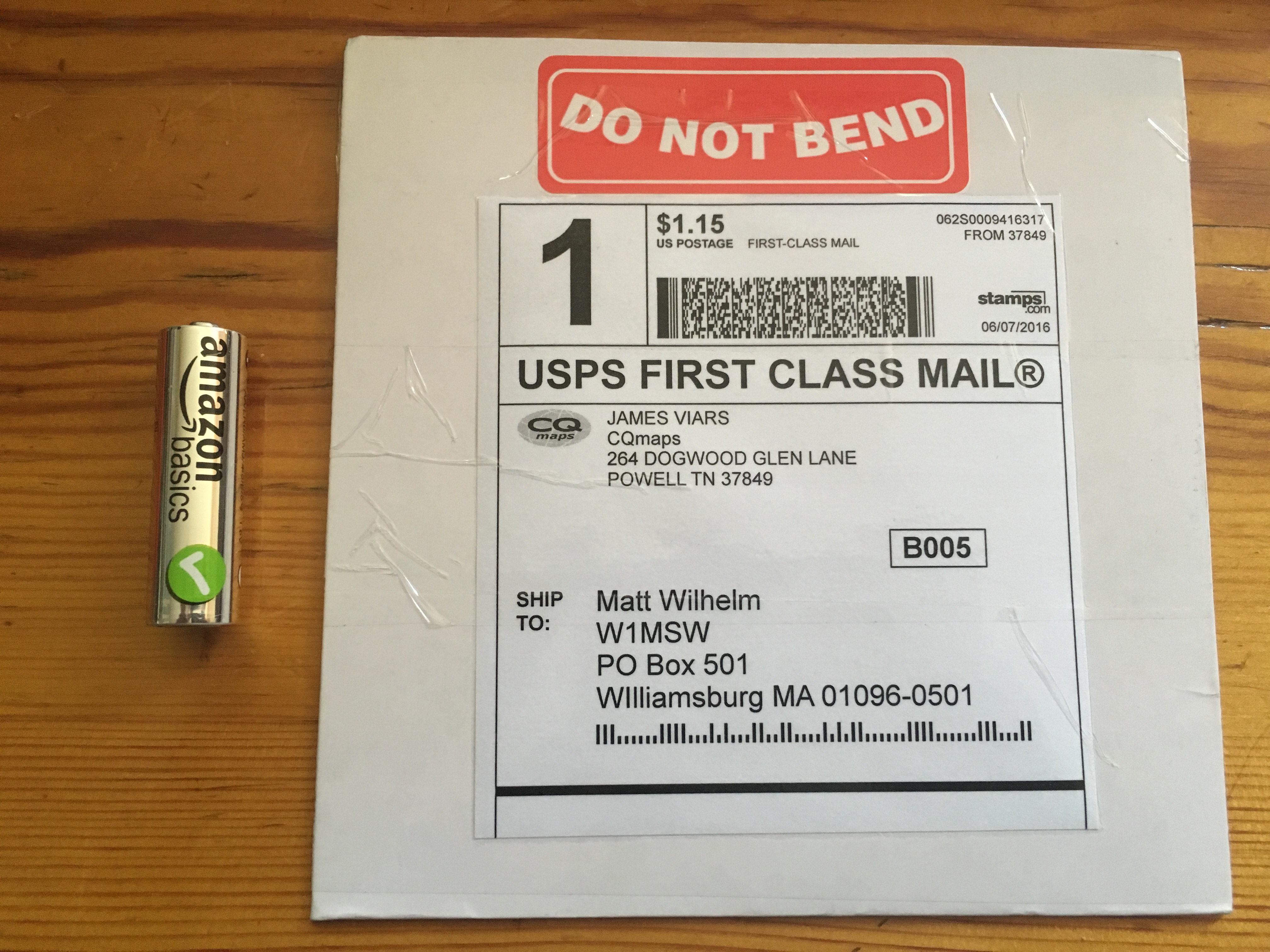
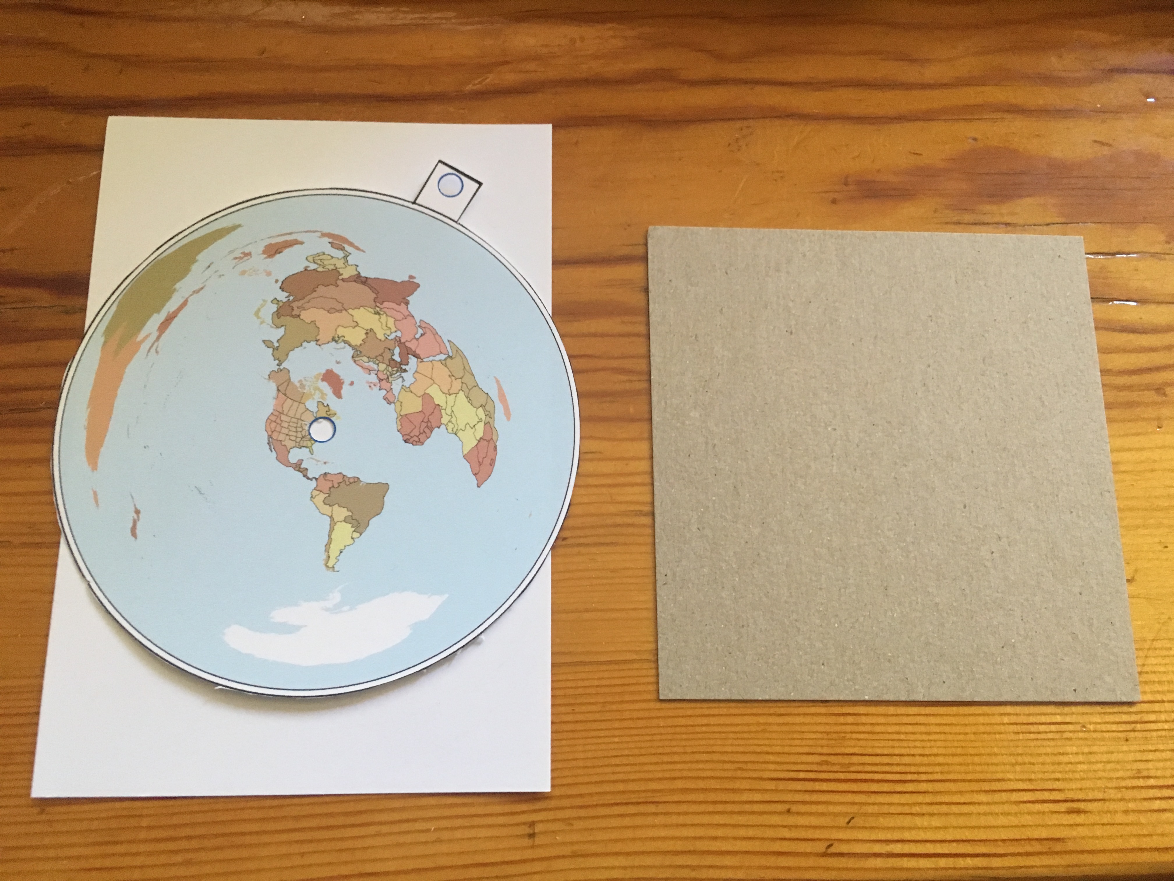
CQMaps does a great job packaging their items. Lots of bending protection and the rotor inserts are small enough to fit in the smallest PO Box without folding the envelope.
I didn’t get a picture of the ERC packaging, but they are put together nicely in a resealable bag with all necessary parts and instructions and software on a CD.
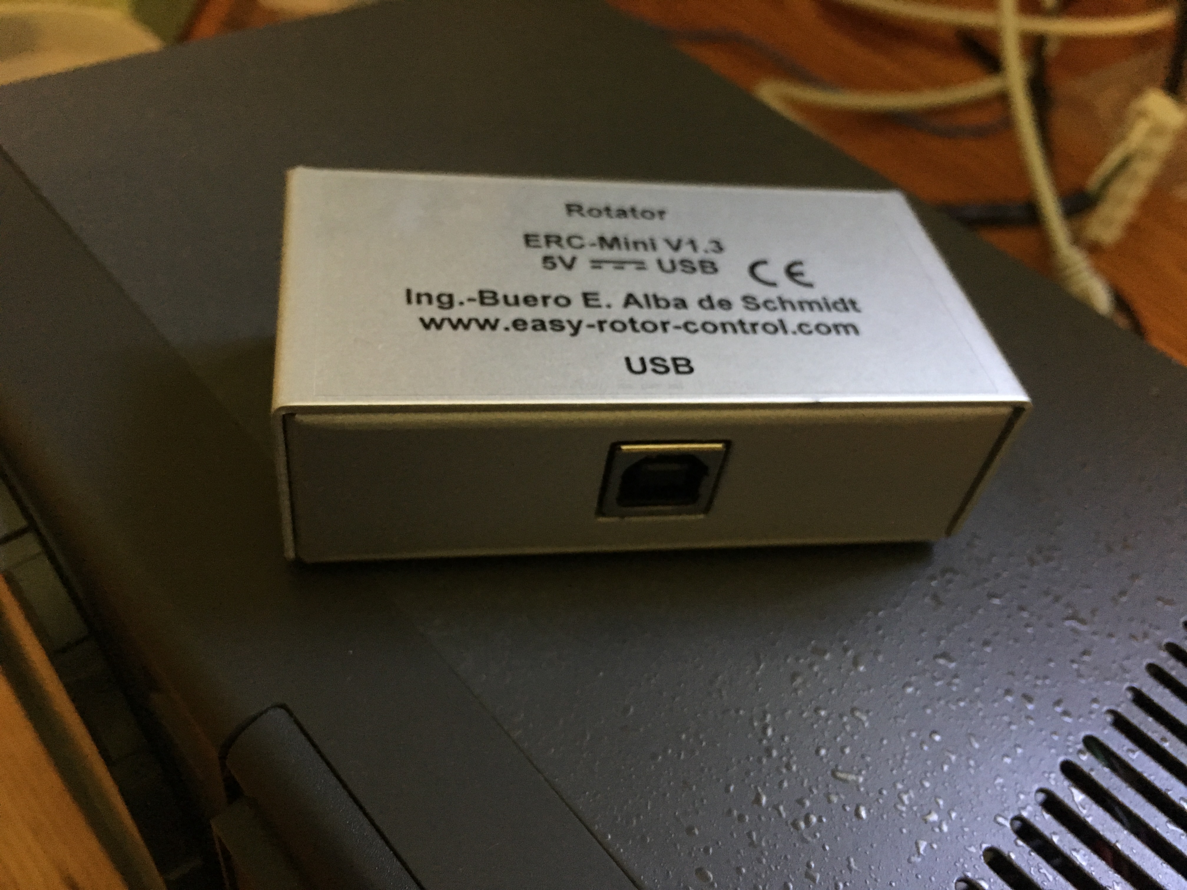
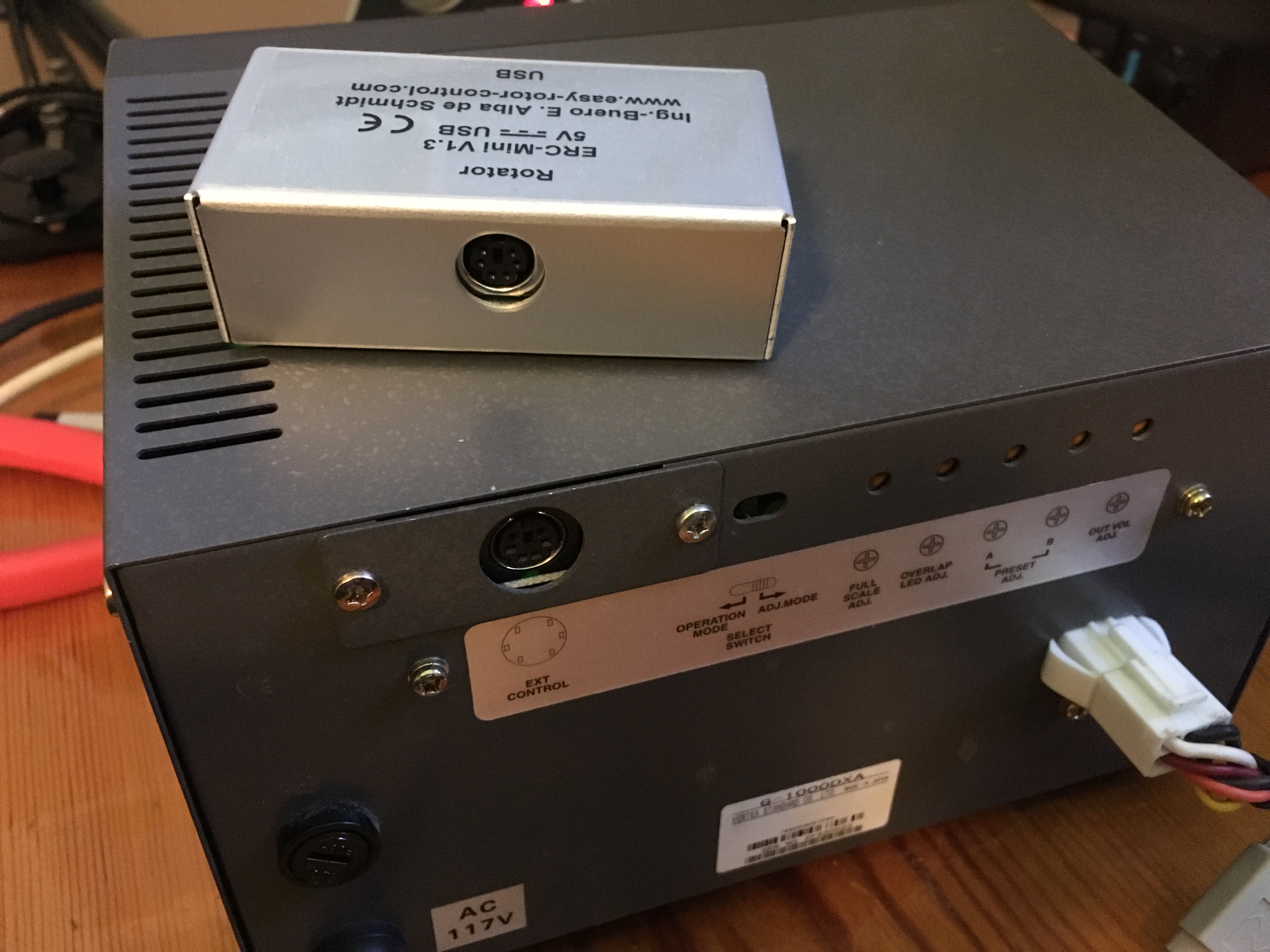
Here’s a couple photos of the pre-assembled interface for the G-1000DXA that connects directly to the 6 Pin DIN on the back of the controller.
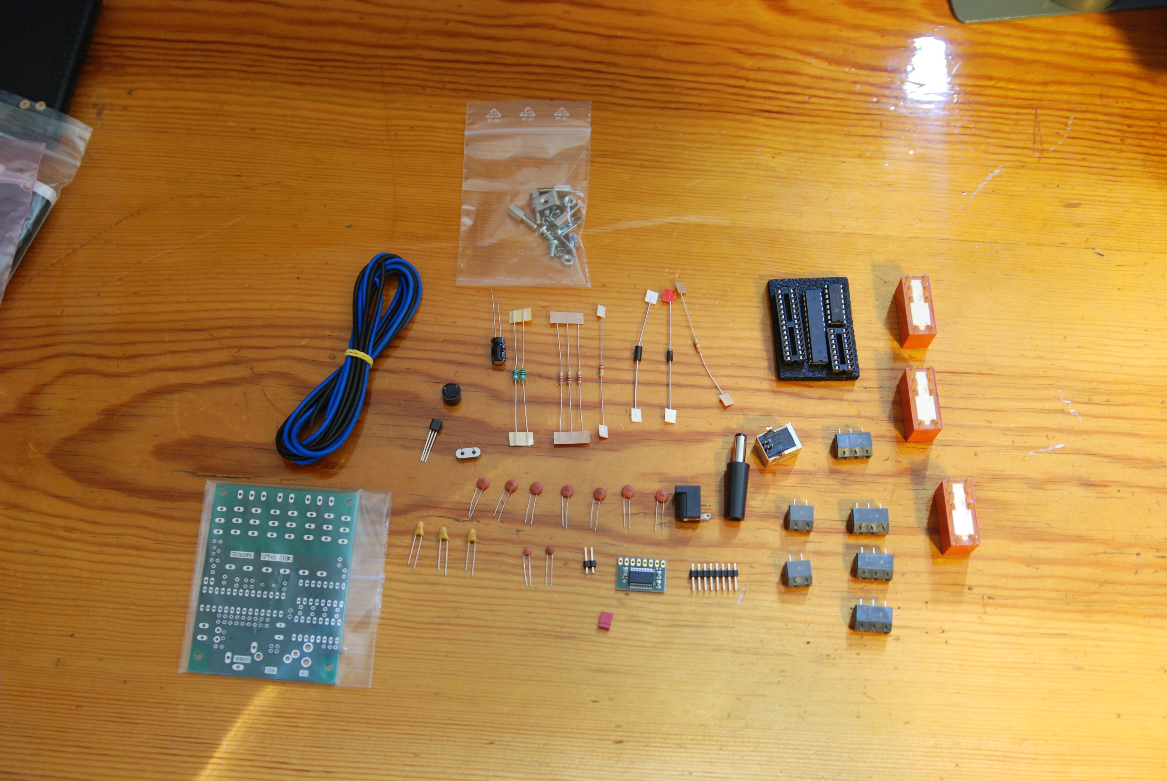
And here is a photo of the parts for the G-450A controller laid out for inventory before assembly.
Solder smoke and poking holes in sheet metal
The most time intensive part of the project is building and installing the interface for the G-450, so I’ll focus on that first.
Building the kit was quite easy and it could easily be done in one evening. For me, it did take a while, but only because I was out of practice and was having trouble carving out the time to work on it. I did run into some difficulties with the instructions, but that probably had more to do with my inability (as a true ham) to read about all of those pesky little details. When I saw large red blocks over parts of the PCB in the documentation, to me that means “DO NOT INSTALL THESE PARTS.” But after reading a little more closely, it actually means “THESE PARTS HAVE DIRECTIONALITY.” So the directions weren’t bad, they just required reading.
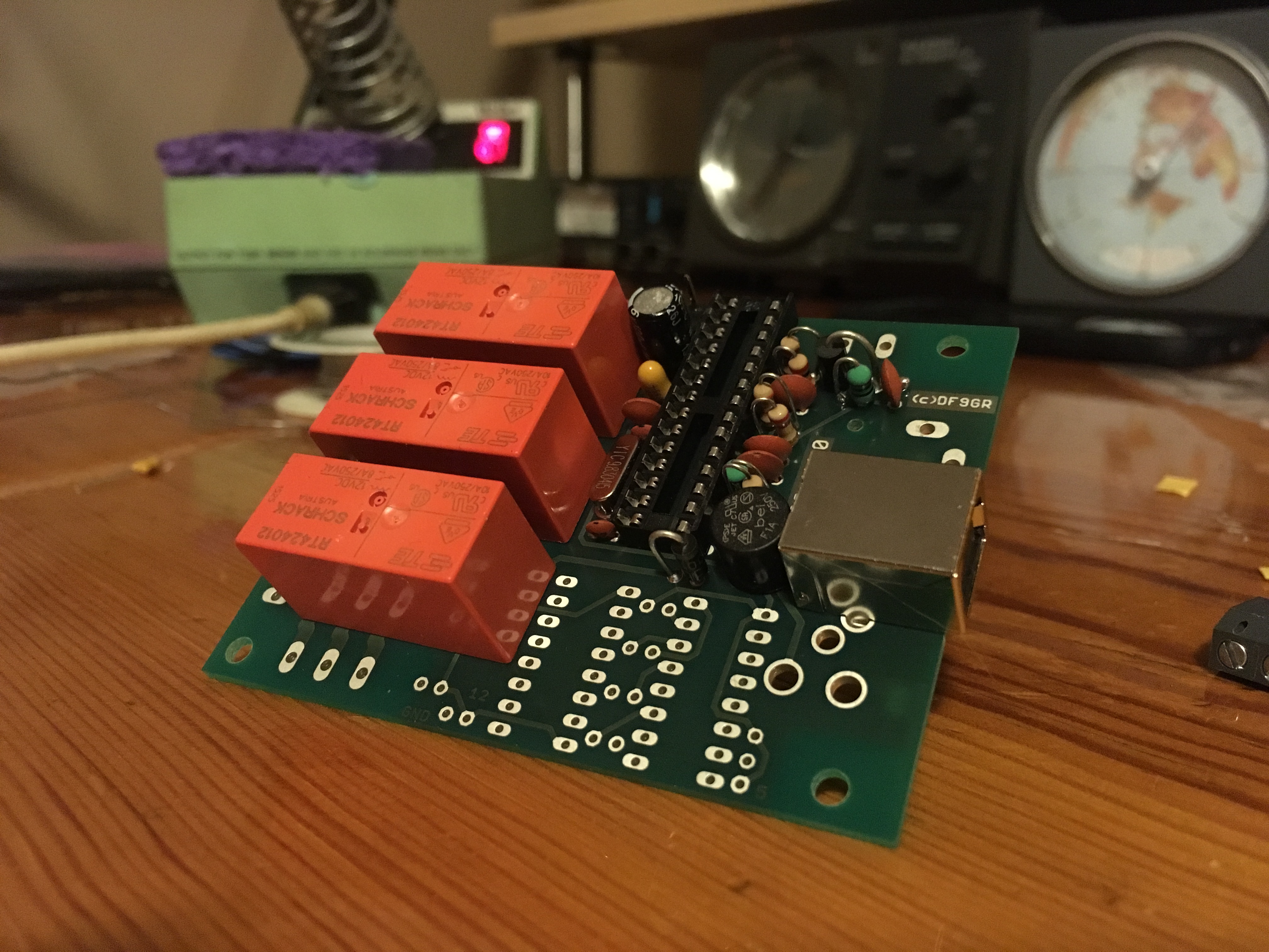
Here’s the build after my first session.
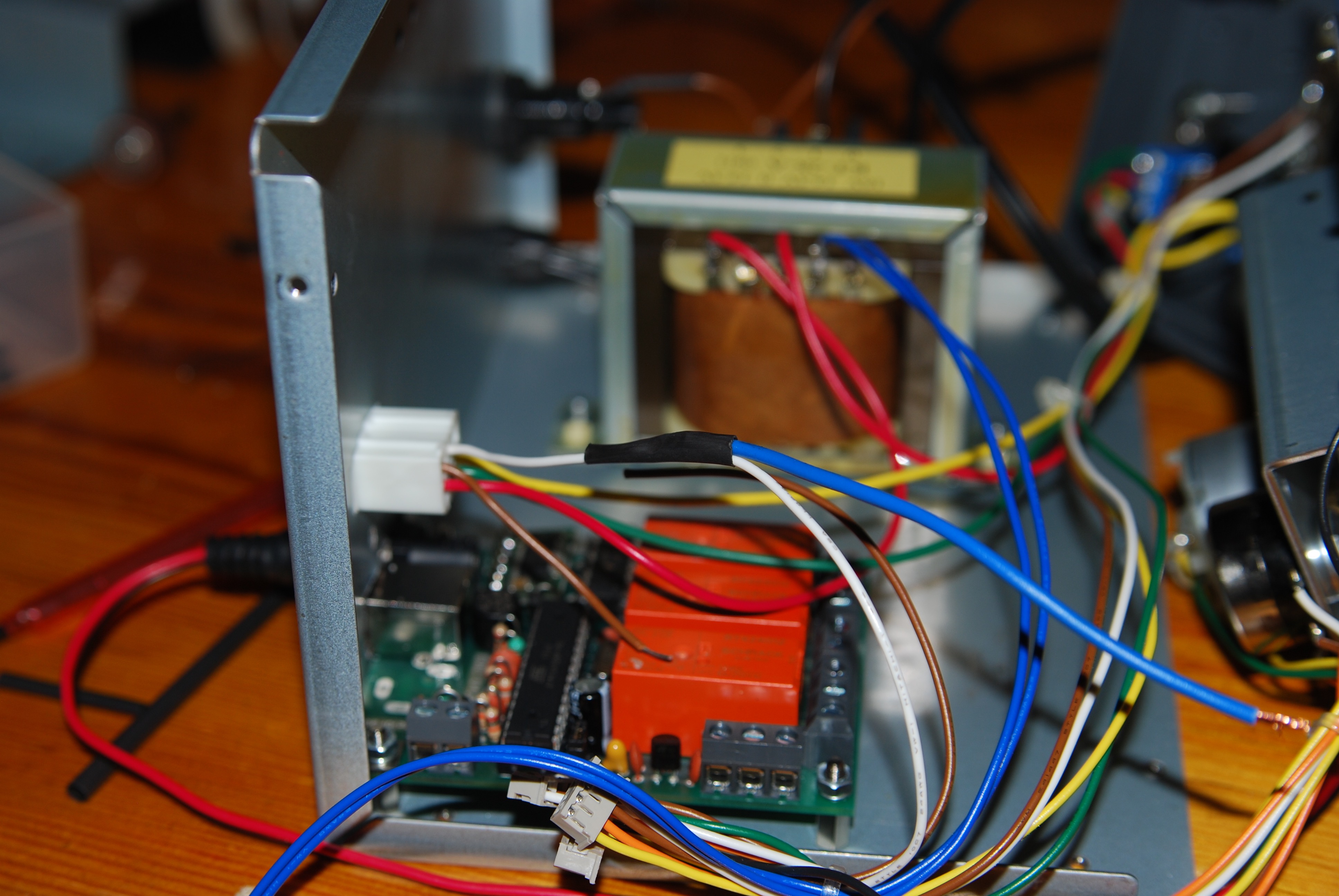
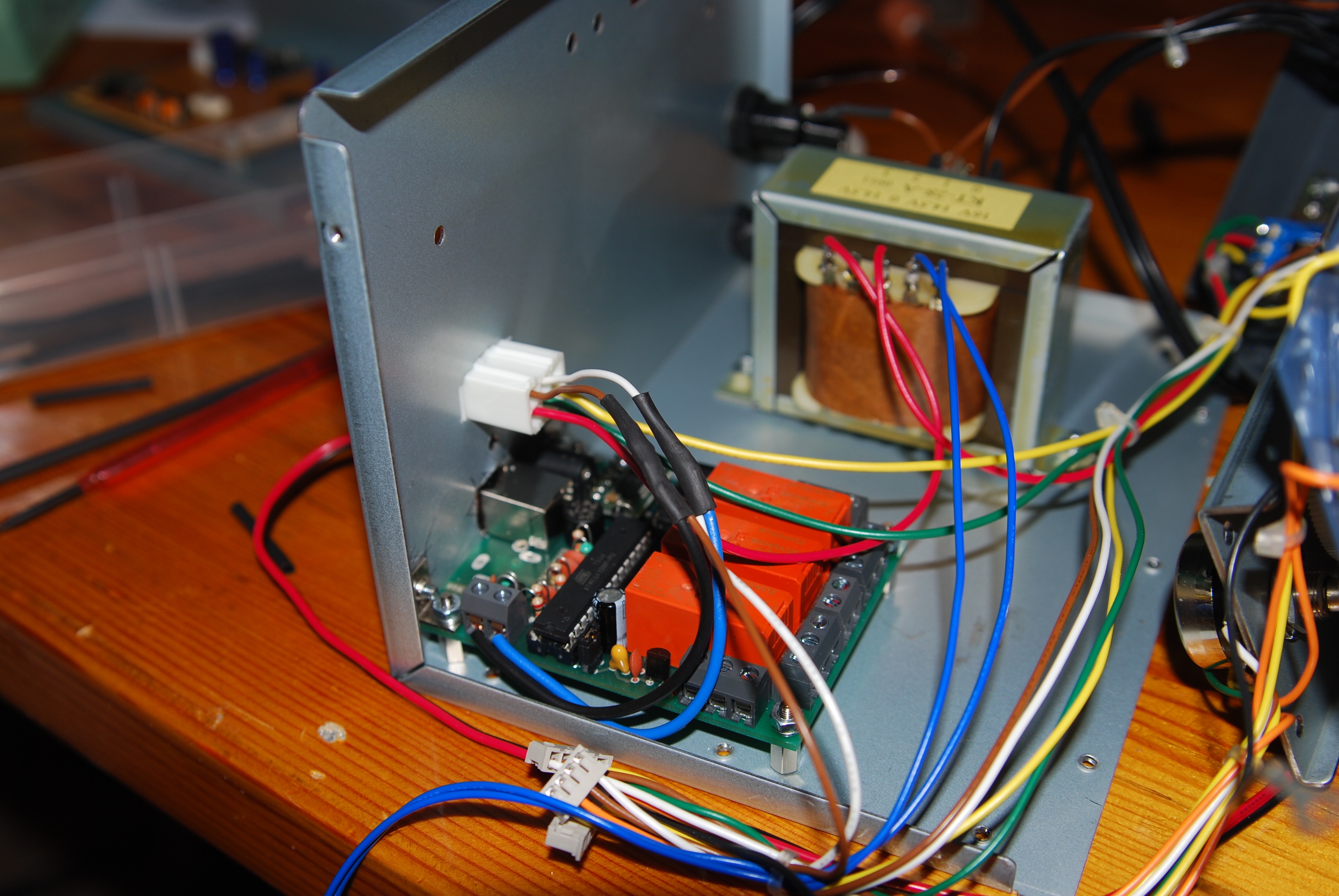
And here is the board with all parts minus the chips and with 12V applied for the first test, which consists of taking a couple voltage measurements on the board. 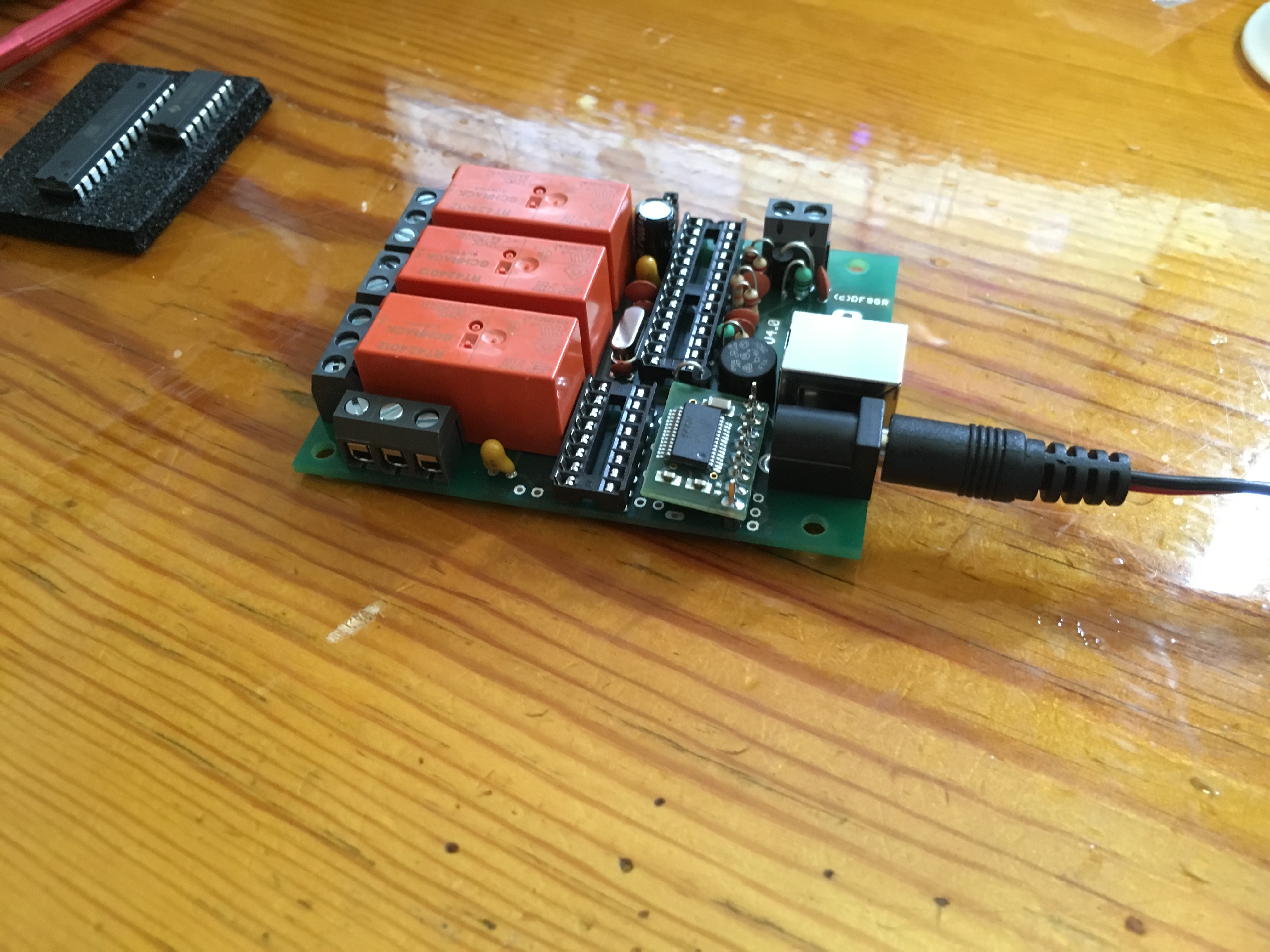
Finally the chips are inserted and the USB cable from the computer is connected. Once the computer recognizes the device and assigns a COM port, you’re ready to finish the final testing process. Testing software is included with the kit and it is as simple as clicking the button labeled “Test.” Once you hear all three relays click, you know everything is working properly. WARNING: There is a longer pause for the third relay to click (break delay), so don’t panic while you wait for what will seem like an eternity.
It works, now what?
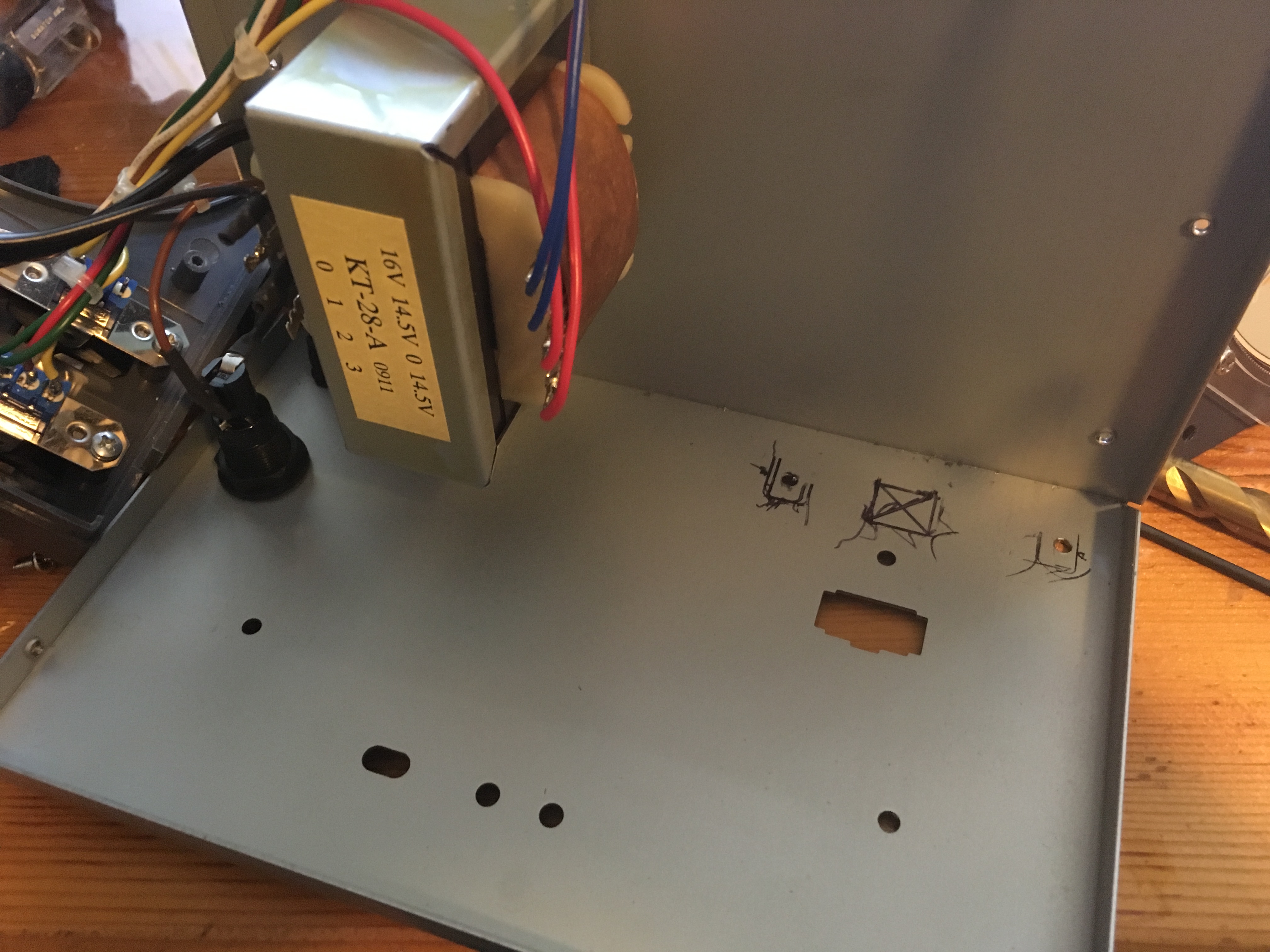
So now we get to the part I’m not so great at: fabrication. I never take enough time and I never have the right tools to line things up and cut sheet metal. So while the installation wasn’t pretty, it was relatively easy to install since the measurements are well documented in the manual.
Marking the case for drilling
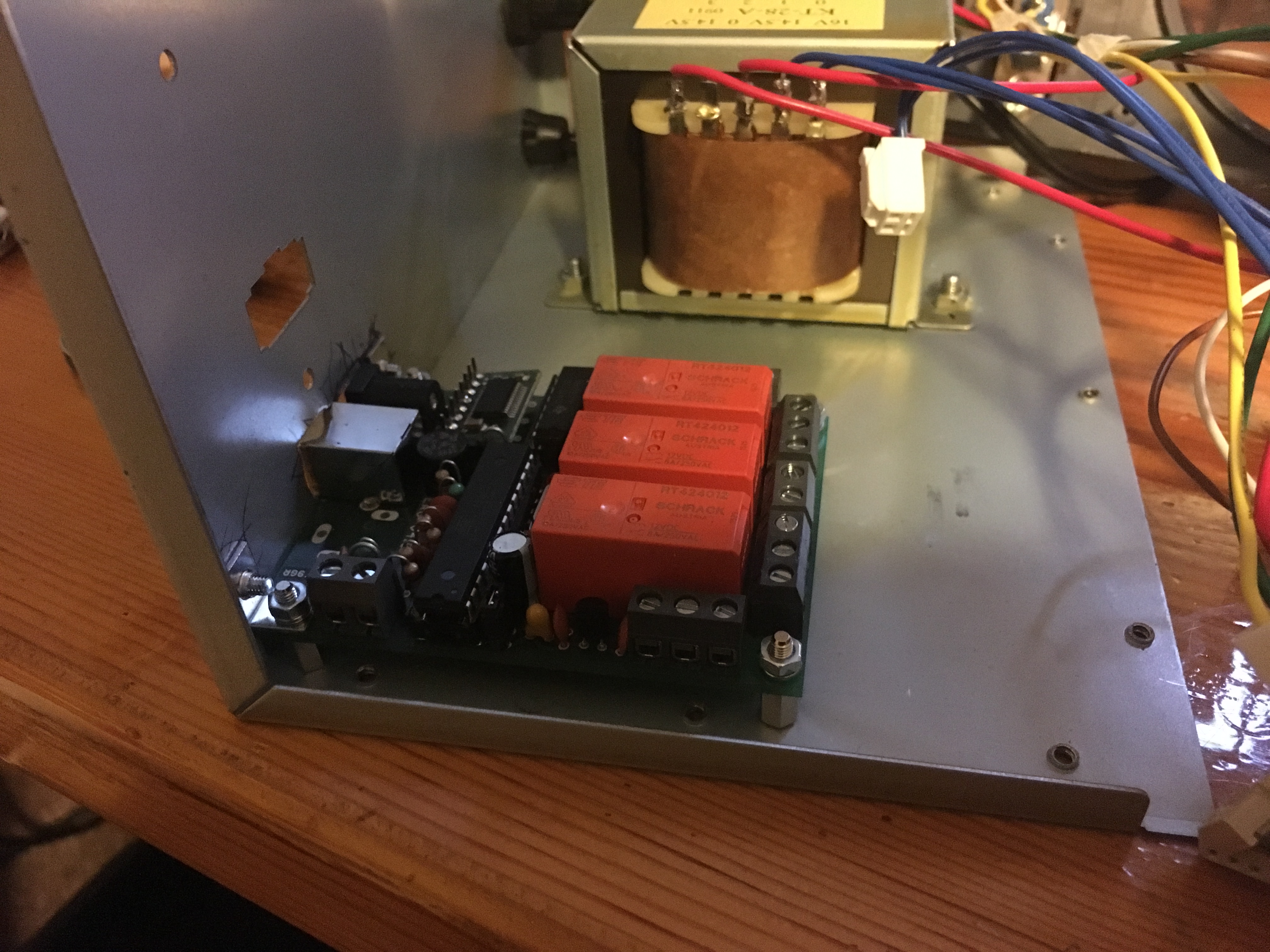
Screwing down the board
View from the back. Good thing no one will ever see it!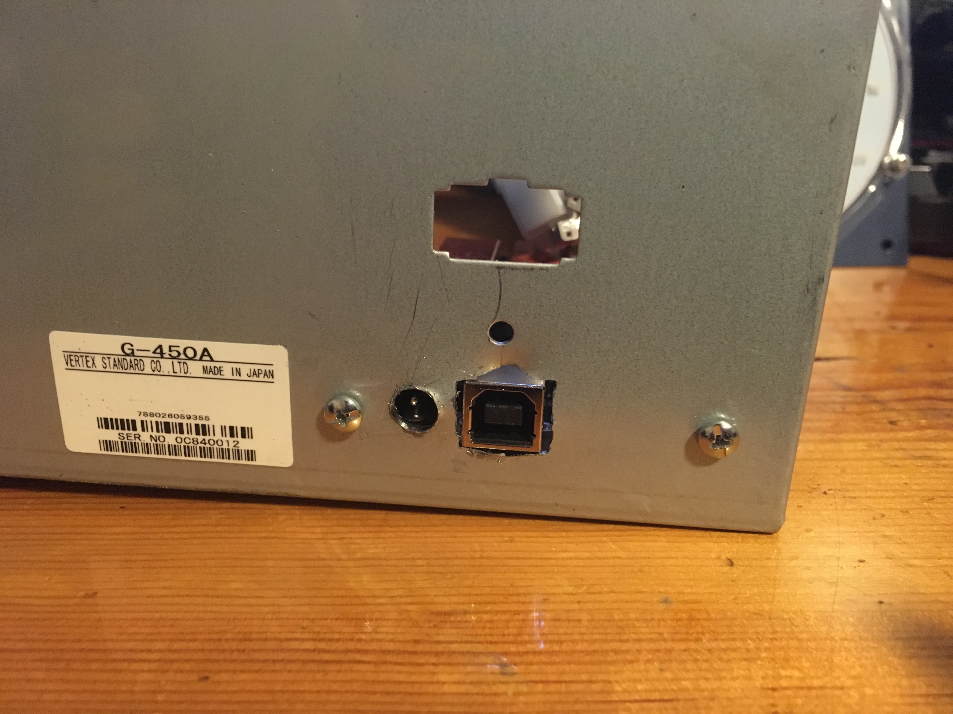
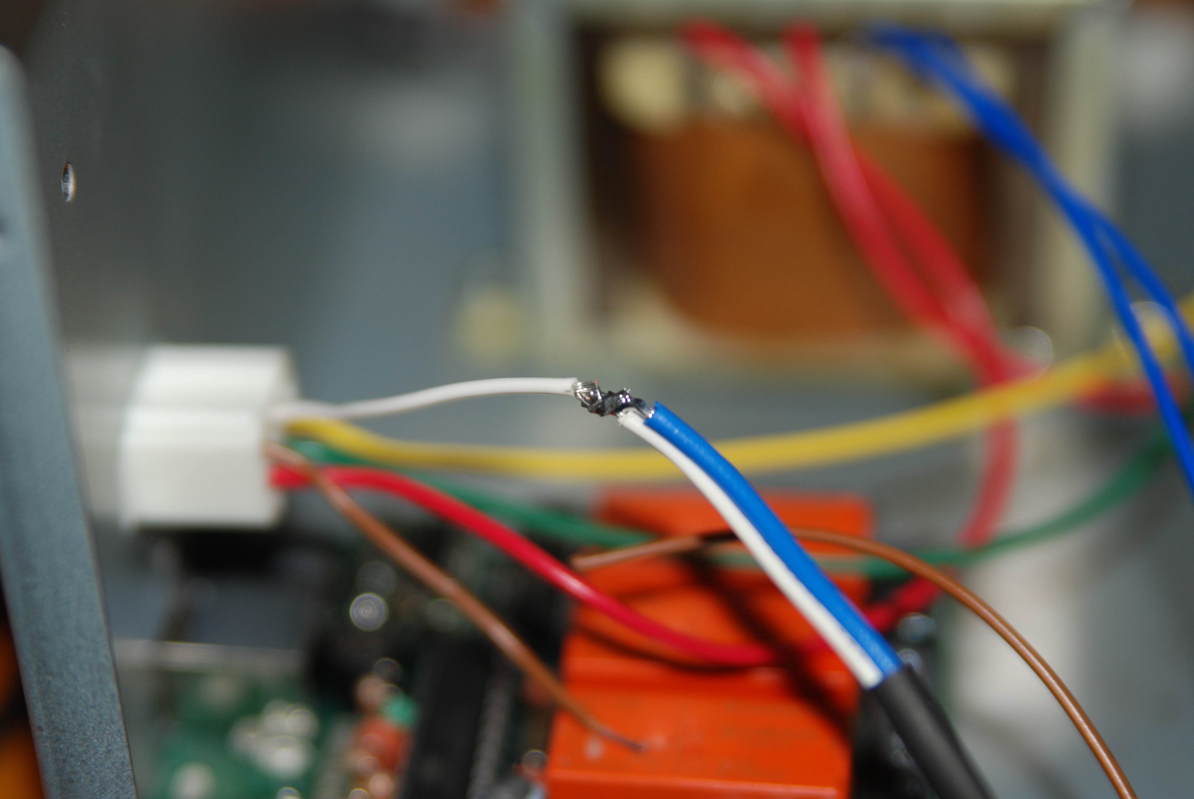
The final stage of the board installation is making the connections from the interface to different locations in the controller box. Two of these locations required tapping a single wire with pinned connectors on each end and no solder points. I decided to just cut the wire and make a three way soldered connection and clean it all up with some heat shrink tubing.
The other connections were to the left and right switches and it was very easy to solder the new, additional wires to the existing solder blobs.
Don’t close up that box yet!
I still needed to change out the bulb and insert the new map. The procedure is exactly the same for both controllers with the exception of a couple screws. One very important screw is in the center of the direction needle in the G-450A that doesn’t exist in the G-1000DXA. James has done a great job documenting the procedure for both the G-450A and the G-1000DXA at CQMaps.
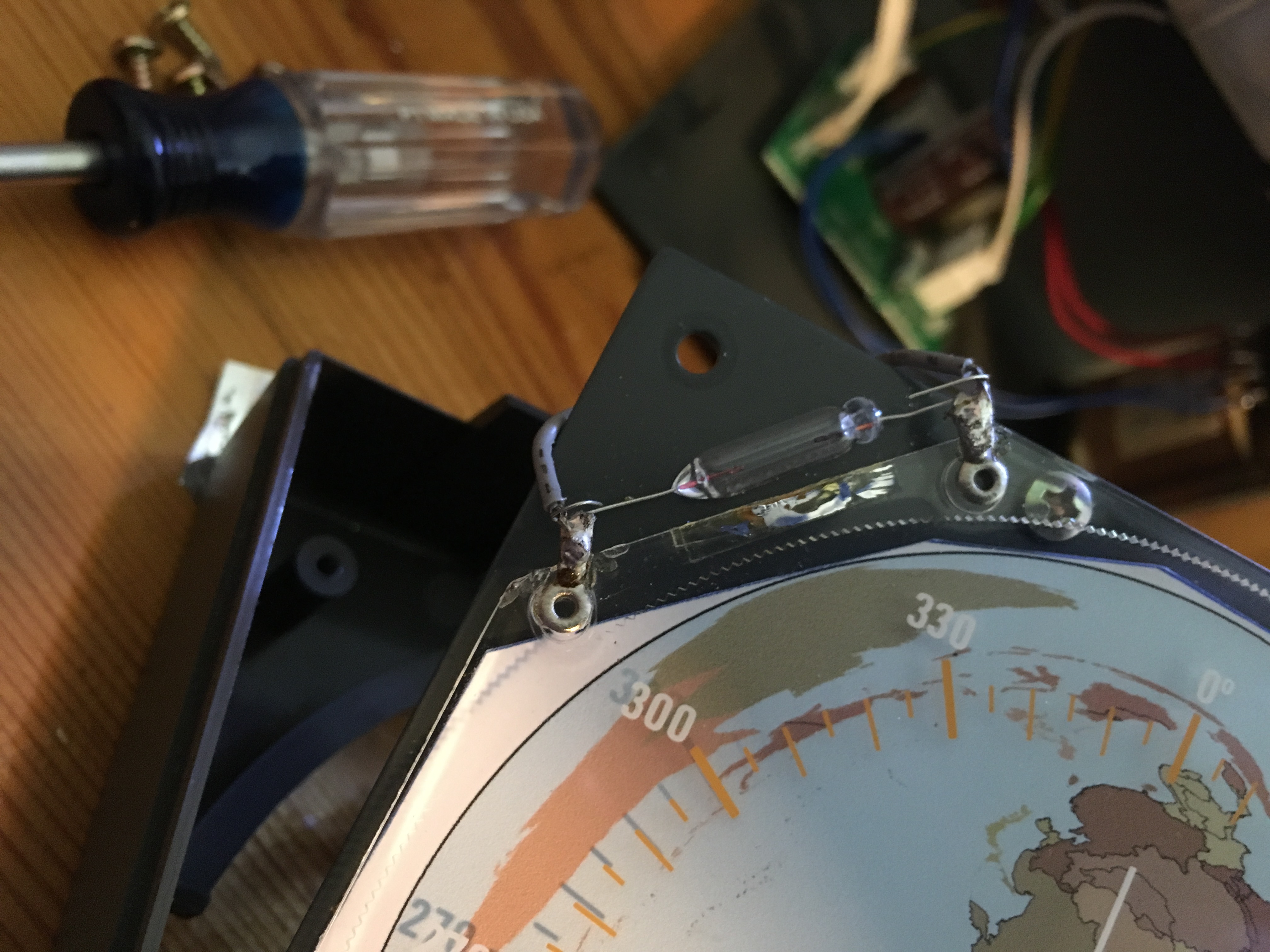
The incandescent bulbs in both controllers are soldered in place with a piece of adhesive reflective foil wrapped around it to help focus light across the dial. You have to carefully peel back the foil and de-solder the bulb. Once you have the bad bulb removed, you can just twist the leads of the new bulb across the contacts on the controller and attach with a little solder. There are also some online retailers that sell LED mod kits or you could make your own, but as I mentioned earlier, I prefer the soft incandescent glow that the original bulb gives off.
Here you can see the foil has already been removed (sometimes you can get one side to stay on) and the bad bulb needs to be removed. It’s very easy to de-solder this by warming up the solder on each lead while applying a little pressure on the bulb to remove the leads from the solder blob.
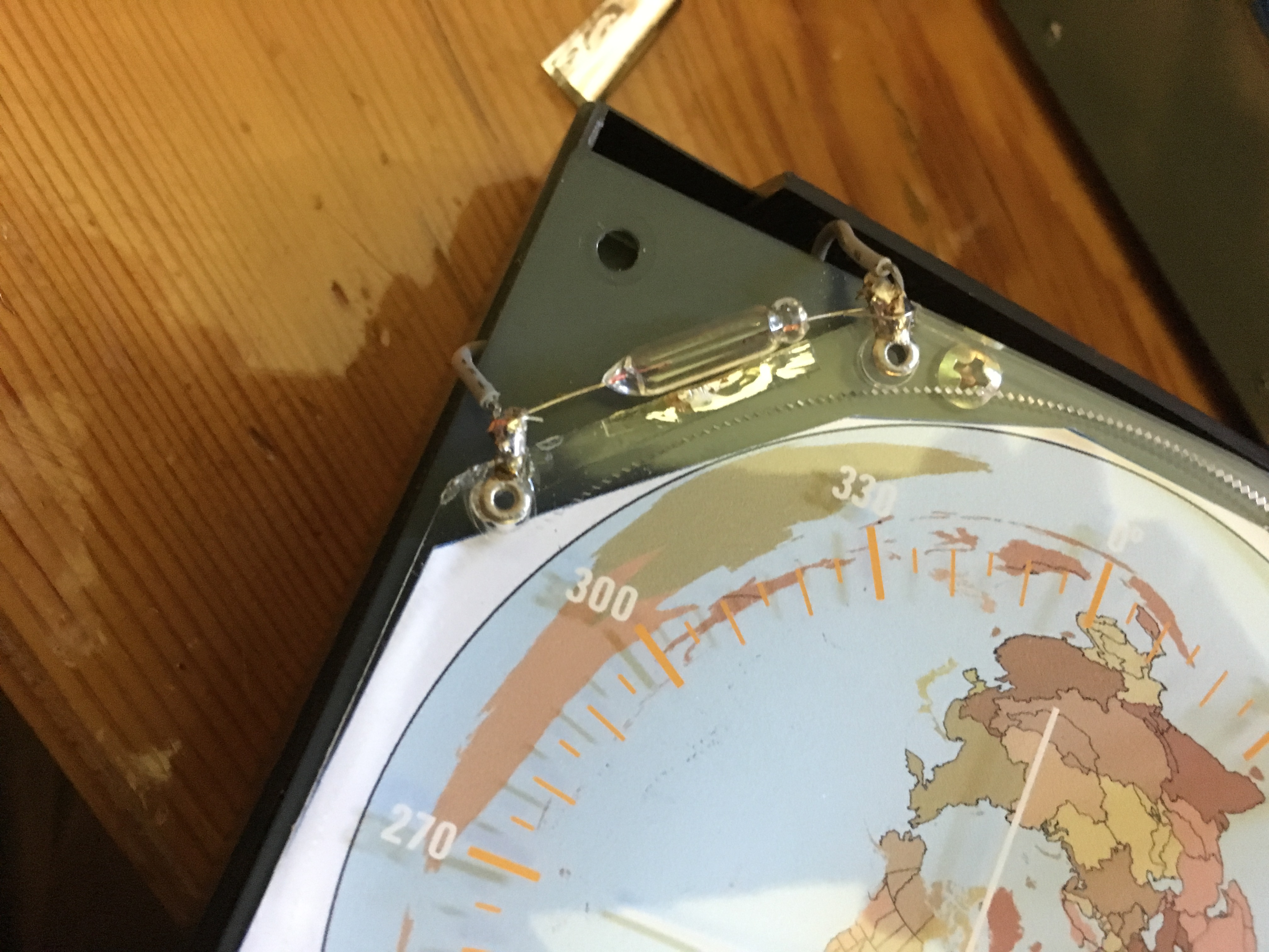
Here is a shot of the bulb completely removed.
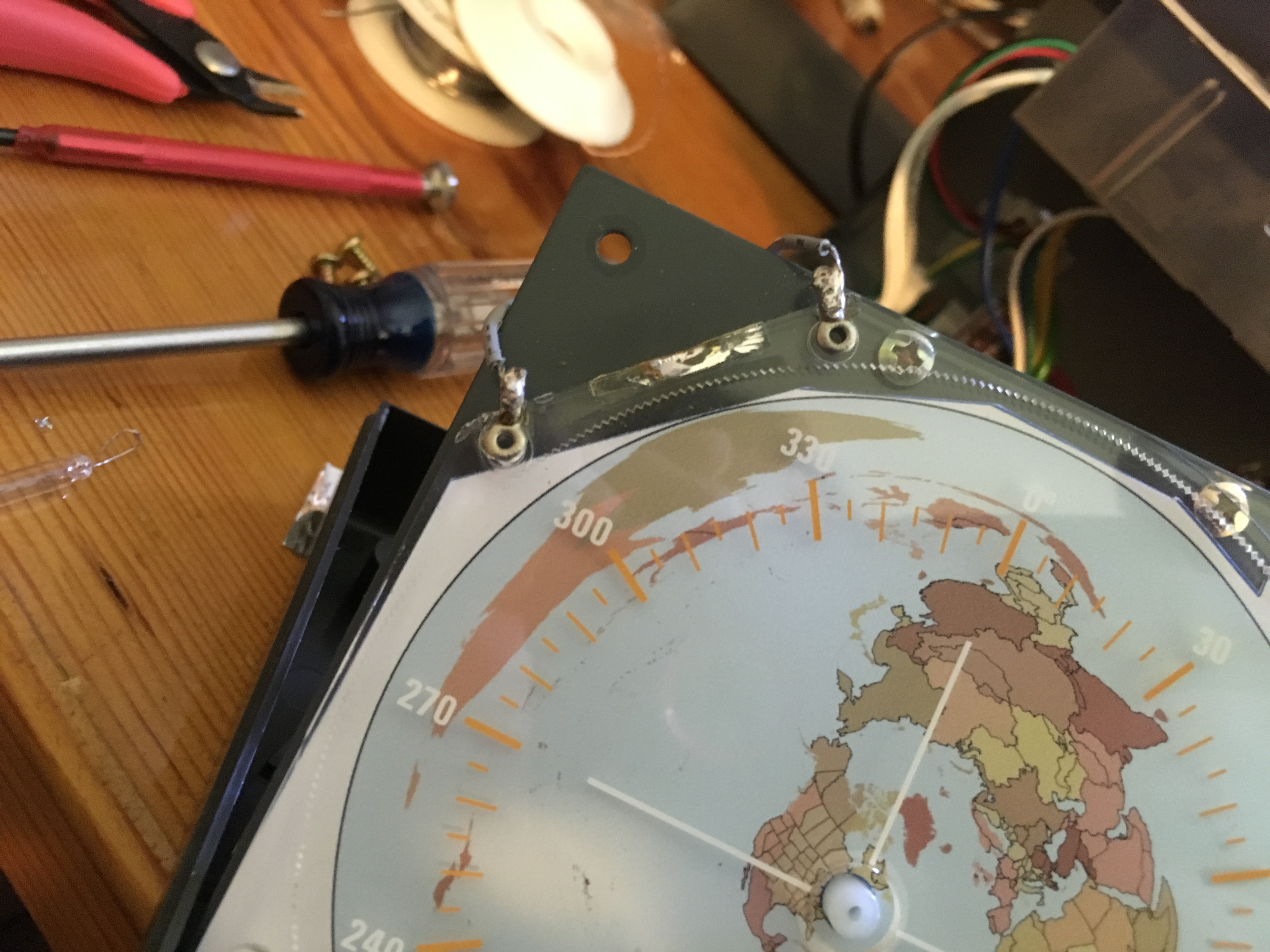
Here I’ve twisted the leads of the new bulb around the old solder joints and will solder them in the exact same spot.
Now that the bulb is in place and the foil has been put back, I can tackle the map insert. Here I have removed the screws holding the faceplate on and the direction indicator. The key on the G-450A is to remove the tiny screw in the middle of the indicator BEFORE trying to remove the indicator. This does not exist on the G-1000DXA.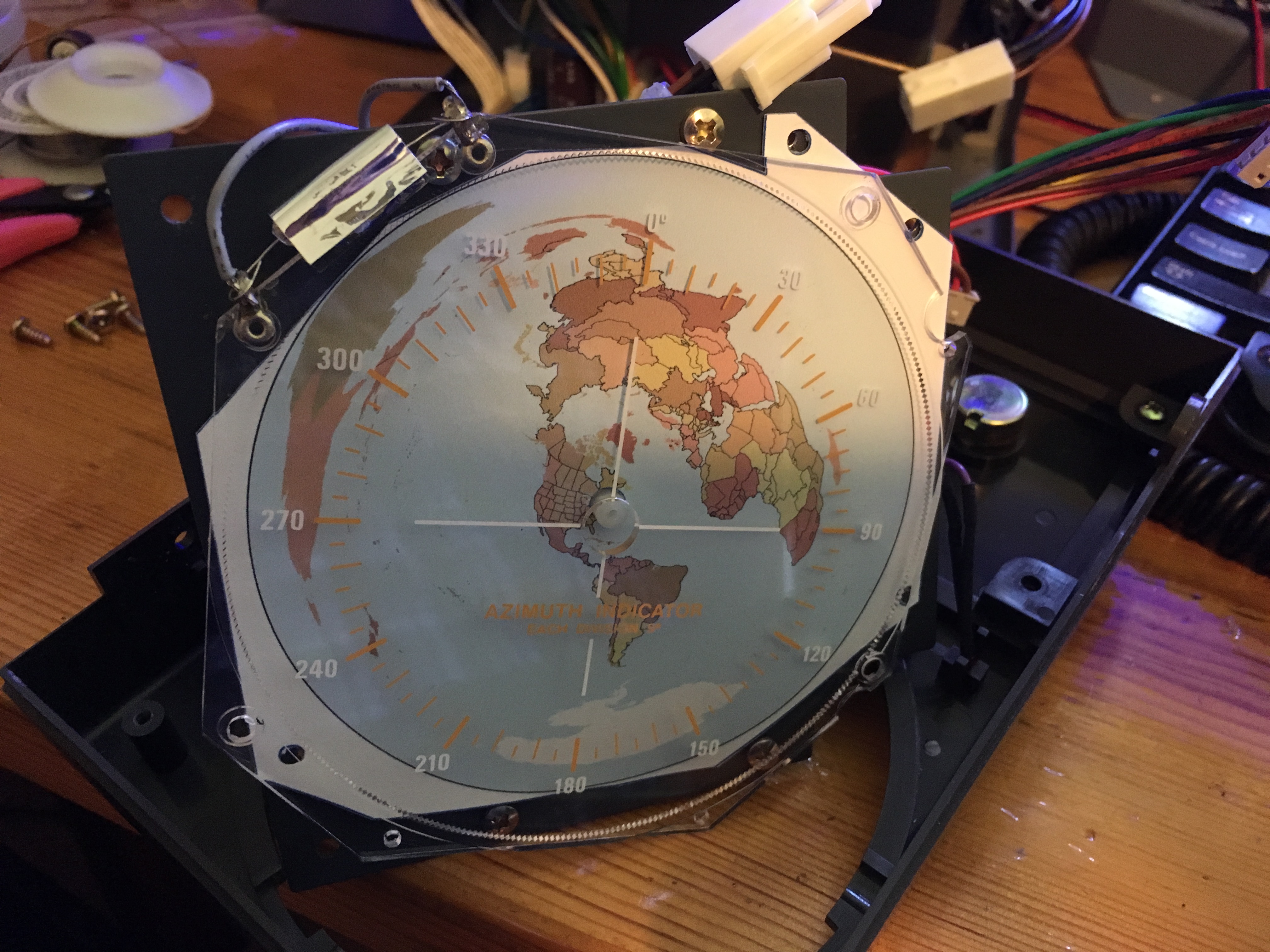
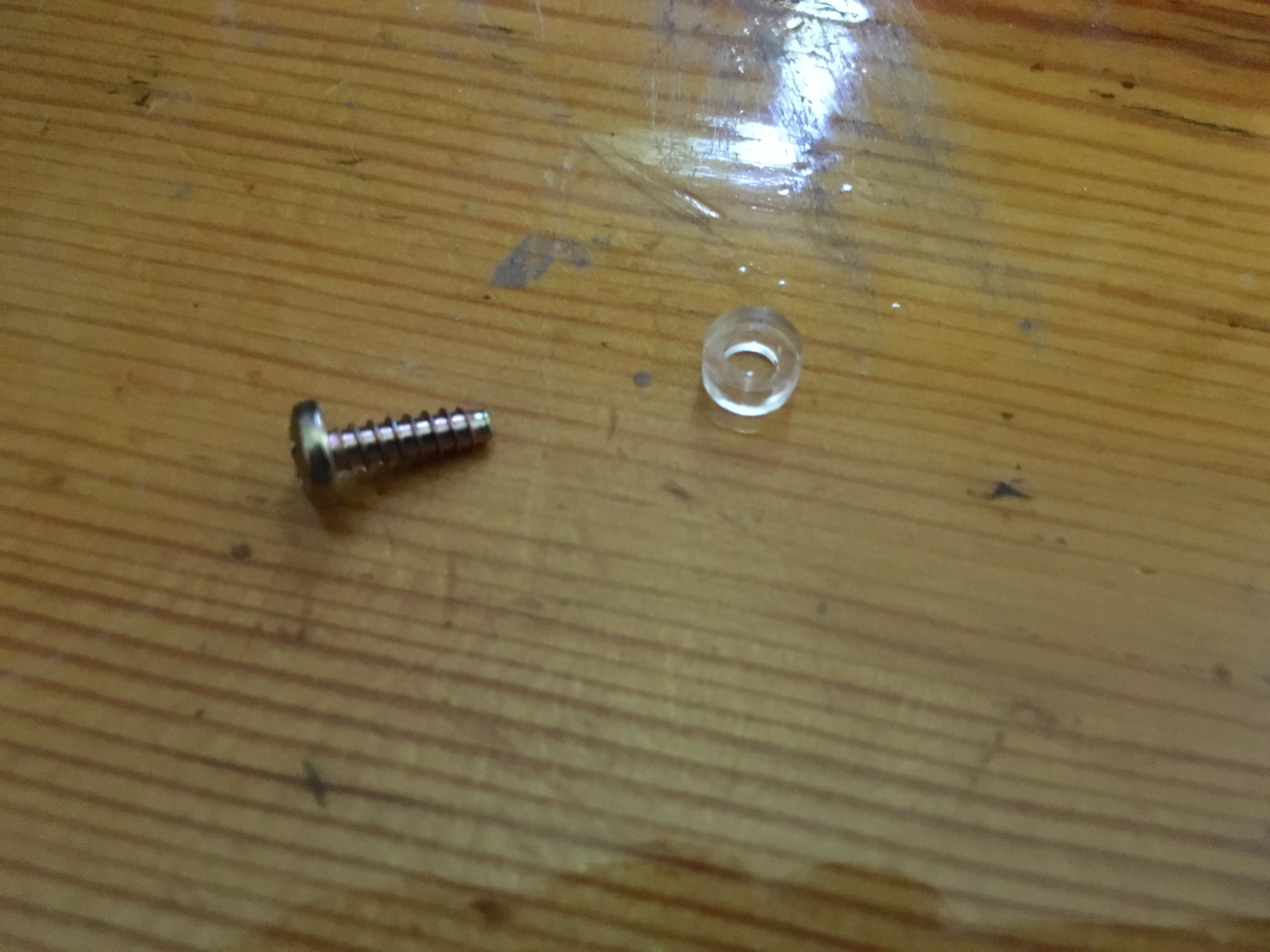
The other trick to this mod is to make sure to not lose the very small, very hard to see plastic washers that live between the plastic dial face and the back of the dial. They are small, bounce like crazy, and very hard to see on the floor!
Configuring the software
So once I finished putting the boxes back together, it was time to calibrate the interfaces and setup N1MM and DXLabs to control the rotors. Calibration was very simple and consisted of opening up the ERC software and starting the process. The software provides step-by-step instructions, which involve manually turning the rotor as far as it will go one direction and clicking a button, then turning it all the way in the other direction and clicking a button. Once this is finished, you can close it and configure the logging software. I have two logging programs that I use regularly: DXLabs Suite for daily logging and N1MM Logger+ for contest logging.
DXLabs
If I had only one rotor to control, I could have configured the rotor control directly in the DXView software within DXLabs, but since I wanted to be able to control both rotors in the program, I have to use a separate rotor control program. It just so happens that the N1MMRotor software that comes with N1MM can be used in stand-alone mode by DXView to control both rotors. Configuration of N1MMRotor is as easy as going to Tools>Setup Rotors and then choosing the COM port and rotor model. Once this is done, you open DXView’s configuration panel and go to the Rotator Control tab. In my case, I checked “Enabled”, choose “N1MM Current” under the Model section and then chose the corresponding COM Port for the rotor that has antennas for each band. Now when I want to use rotor control with DXLabs, I start up N1MMRotor and DXView. You can create a shortcut to N1MMRotor in your taskbar or on the desktop to make it easier to find and open. This is all well documented on the DXLabs wiki.
N1MM
Setting up N1MM Logger+ is even simpler if you’re already using N1MMRotor with DXView and the process is well documented on the N1MM Wiki. If you’re using N1MMRotor with DXView, close the program and then open up N1MM. Configuration is done in Config> Configure Ports, Mode Control, Audio, Other…>Antenna Tab. There you configure which bands are associated with which rotor.
So, how is it?
One of the common themes I hear in the various “improve your contest score” talks that I’ve attended is to simplify your station and make it easier to control in “Hour 48.” Another thing I learned early on working in IT is that the less you take your hands off the keyboard, the better. Adding these interfaces for the rotor controllers is a really nice feature that helps meet both of those goals. Being able to choose a hot key in the logging software allows me to get the antenna headed in the right direction while keeping my focus on working the station I’m trying to put in the log. These affordable controllers work great and the kit version for the G-450 was an easy build. The rotor maps were also a nice addition. Having a Great Circle Map on the rotor isn’t essential if you already know where to point your antennas, but they do look really nice and are customized to be centered on your location. If you are thinking of trying any of these mods and have questions, don’t hesitate to contact me!
73,
W1MSW